 IntroIntro
Like many radio amateurs I have collected a large collection of recharchable batteries. Some are over 10 years old an others were obtained from sources like flee markets and disassembled broken laptops. I have noted that some packs seems to have degraded over the years and could only store a fraction of their promised capacity. The cheap solution was to charge the battery, hook up a resistor and a voltmeter and regularly check the voltage of the battery. As this is rather time consuming if you discharge with .1 C and you often tend to forget the check the voltage I decided to make a small device which would automate this.
Nowadays you can get microcontrollers with built-in A/D convertors
for a few Euros so this should not be a problem. The Battery Capacity Meter
descibed below is the result.
The principle of the meter is very simple:
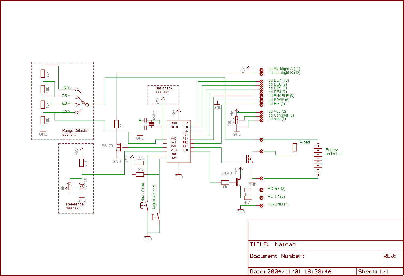
You hookup a fully charged battery and load resistor to the meter, enter the value of the resistor and the cutoff voltage and start a discharge cycle. The meter will switch on the load using a power mosfet and continiously measure the battery voltage. To precisily measure the voltage a reference diode is used. During the discharge you can select to display the current voltage and current or the time expired and capacity so-far. If the cutoff voltage is reached the load will be disconnected and the capacity will be shown on the LCD display.
Because a resistor is used as load and not a current source the current will vary over the discharge cycle. A Lithium/Ion cell will e.g. supply a voltage of 4.1 V when fully charged and 3.3 Volt when it is depleted. With a 10 ohm load the current will vary from 410 mA at the start to 330 mA at the end of the discharge cycle.
The meter will however use a sample every minute and calculate the supplied power in milliAmpMinutes during the last minute. This is totalled to display the overall capacity of the battery.
 To
allow plotting of the discharge curve you can set an interval to store the measured
values, e.g. once every 5 minutes. After, or during, the discharge this data
can be transferred to a PC via an RS-232 interface. With the use of a spreadsheet
program a discharge curve can be plotted. As only 128 samples can be stored
in memory the battery should be depleted before this buffer runs full. The fastest
sample rate (once every 5 minutes) allows a maximum discharge time of 10.5 hours,
the slowest sample rate (once every 20 minutes) allows a discharge time up to
42 hours.
To
allow plotting of the discharge curve you can set an interval to store the measured
values, e.g. once every 5 minutes. After, or during, the discharge this data
can be transferred to a PC via an RS-232 interface. With the use of a spreadsheet
program a discharge curve can be plotted. As only 128 samples can be stored
in memory the battery should be depleted before this buffer runs full. The fastest
sample rate (once every 5 minutes) allows a maximum discharge time of 10.5 hours,
the slowest sample rate (once every 20 minutes) allows a discharge time up to
42 hours.
To enable transmission of the data to the PC just press the adjust/send button.
This can be repeated multiple times (as long as the meter is not reset).
 Specification
By selecting other values for the divider network and/or changing the constants in the software it is possible to change these specification. In the current implementation, intended for testing AA, AAA and Li/Ion batteries the current software is setup with the following specs:
Voltage ranges: 2.5, 5, 7.5 and 15 Volt, resolution: 10 mV in
the lowest setting, 50 mV in the highest setting
Load Resistor: 1..100 ohm (specified in ohms)
Curve sampling times: 5, 10 and 20 minutes
Power supply: 5 V regulated or 4 AA or AAA NiCd cells (4.8 V)
Current: 5 mA (40mA if the Backlight is switched on)
When the meter is switched on the display will show a version
message like this: "Cap.
Meter V 1.6".The meter is controlled by two push
buttons, an Adjust/Send button to modify the settings or to send the data over
the serial interface, and an Enter/Go button to advance to the next menu or
start the discharge cycle.
When the enter button is pressed the backlight is turned on and an internal
power check is performed. If the battery voltage is below 4.5 Volts the message
"* Battery low
*" is displayed indicating that the meter may run out of power
during the next measurement cycle, you decide to ignore this and pres the Enter
button again.
Now the external settings should be entered, in the next menu the Voltage Range
is specified ("V
Range 05.00V"), use the Adjust button to select the range
which is required, use the Enter button if the correct setting is shown. The
next step specifies the value of the load resistor which is used to discharge
the battery ("Load
R 050.0 ohm"). Select the proper value and press the Enter button
again. Please note that the load resistor should be identical to the specified
value, especcially with low resistor values (e.g. 10 ohm), difference with the
actual value (e.g. 10.3 ohm) will introduce large errors in the accurary of
the result. Use a parallel resistor to end up with a load with is a multiple
of .5 ohm !!
Finally the cut-off Voltage (The voltage at which the meter will stop discharging
the battery) should be entered ("V
Cutoff 3.00V"). NiCd and NiMH batteries are depleted if the
voltage reaches 1.0 V per cel, Lithium-ion 3.0 V per cel and Lead-acid based
batteries at 1.75 V per cel.
After accepting all settings the voltage of the battery-under-test
is shown, you can now connect the battery and load resistor. If the enter button
is pressed the load will be switched on an the measurement will start, if you
made an error during the entry phase just switch the power of the device off
and on. During the discharge the actual voltage and current are displayed. Pressing
the Enter button will toggle between this display and a display where the duration
(HH:MM) and capacity so-far are displayed. Pressing the Adjust/Send button will
transmit the discharge curve and capcity. Pressing either button will also turn
the backlight on for a brief period. When the cut-off voltage is reached the
load resistor will be disconnected and the resulting capacity will be shown
("Ready 01365
mAh"). You can now connect e.g. a PC and receive the Discharge
Curve. Initially every 5 minutes the voltage is stored, when more than 128 samples
are received, the system will switch to sampling once every 10 minutes and so
on.
The best results (most accurate) are achieved with discharge durations of a
few hours up to 15..20 hours. At very short durations (high currents) the measurement
is influenced by the inaccurary of the load resistor (e.g. influence of the
wiring, connector and MOSFet ON resistance), with very long durations the accuracy
if effected by the dynamic range of the internal floating point variables.
To be described
Most components are not critical, I used whatever was available
in my junk box. The exception is the divider network: I used 1% resistors and
selected matching pairs using my ohm-meter. For the 2N5401 any low power pnp
transistor will suffice, for the BS170 any low power n-channel fet will do.
For the power mosfet you can also use any type although logic-level FETs are
recommended. The important issue is the Rds(on) resistance, this should be as
low as possible so preferably select e.g. at least an 20 Amp type as they have
"ON" resistances which are lower than 0.05 ohm (e.g. the BUZ11A).
This seems overkill as you will normally discharge with currents less then 1A
(At least, that's how I use the device) but the ON resistance is the critical
factor here.
 Possible
enhancements
Possible
enhancementsI like to live dangerous, so mistakes duringusage (e.g. reversing
the polarity of the test battery) will damage the meter.
The design can be changed to prevent this, also the accuracy can be improved.
Some possible enhancements are listed below.
| 1.3 | 2004-11-02 | First released version |
| 1.6 | 2004-11-09 |
The sampling interval is automatically calculated, no user specification
is required |
Where can I get the software ?
Generic version (LCD display 16 * 1 line)
Batcap 1.6 generic (16*1 display) source files
Batcap 1.6 generic (16*1 display) HEX binary
Special version for a SAMSUNG HK333 fax display
Batcap HK333 source files
Batcap HK333 HEX binary
2004-11-01 - Initial (incomplete) version of this page
2004-11-09 - Updated to reflect the functionality of BatCap version 1.6
![]()